
A 12 volt trigger hub
 The "12v Trigger" is a control mechanism that allows one device in a system to turn other devices on and off.
These jacks started showing up on mid-priced receivers in the late 1970s. Originally they were mostly to let a pre-amplifier turn a power amplifier on and off. But, as home theatres caught on they found other uses. Triggers can now be used for all kinds of things like turning on projectors or auxiliary amplifiers, raising and lowering screens, even managing lighting.
The Trigger protocol is not complex. It's a simple "wake up" signal to another device. When you turn on a device with a Trigger Out the port is energized with 12volts. When you turn it off, the port is reset to 0volts. Any device with a Trigger In connected to this main device will be wakened from standby when the Trigger is asserted and when the Trigger is released it returns to standby mode.
For example:
With Trigger ports, your pre-amplifier can control a power amplifier. Turning on the pre-amp wakes the power amp from standby. Turning off the pre-amp lets the power amp go back to sleep.
A number of new products, equipped with trigger ports have recently started showing up on the market. I wanted to recommend a Trigger Hub for them so they could manage their systems from one central power switch. To my surprise, there simply aren't any Trigger Hubs available. For reasons mysterious, it's not something anyone actually makes or sells although you would think it's a natural addition to any complex setup.
So, to fill the gap, here is a very simple 4 output Trigger Hub you can build for yourself...
Parts you will need
 This is not a particularly parts intensive project, but you will need to acquire some bits and pieces if you don't already have them. Generally your best source is a local electronics parts dealer but I've also included Amazon links for each part.
-
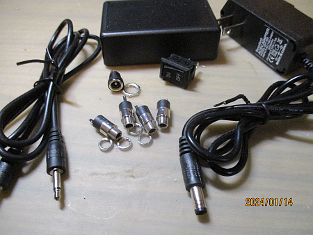
1 x 12 volt power brick. The minimum recommended current here is 500 milliamps for a 4 port hub. Higher current ratings are okay. The one I had on hand is rated for 1 amp.
From Amazon: 12v 1a -
1 x Panel mount barrel jack to connect with your power brick. Depending on the power brick there are two very common sizes: 5.25 x 2.1mm and 5.25 x 2.5mm. You need to pick the one that matches your power brick.
From Amazon: 5.25 x 2.1 or 5.25 x 2.5 -
4 x Stereo 3.5mm phone jacks. The three pin type is best. Having extras is a good idea since you can add more ports as described in the next section.
From Amazon: 20 Pack -
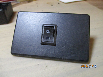
1 x Single Pole Single Throw switch. I like a rocker switch for this project but bat handle, slide or push-push switches will also work just fine. The minimum rating is 24 volts at 1 amp.
From Amazon: 5 Pack -
1 x Plastic project box. For my 4 port build I've used an 80 x 50 x 26mm (3.15" x 1.97" x 1.02") enclosure. If you are adding extra ports (explained below) or would prefer a different style, you will need to pick one that fits your needs.
From Amazon: 5 Pack -
22 or 24ga Hookup Wire, for the internal connections. I strongly recommend using three colours, one for the positive power, one for the positive switched and one for the negative connections.
From Amazon: 6 Colours -
Trigger cables. You will need cables to connect the Hub to your devices. You can purchase them or you can make your own very cheaply as described below.
From Amazon: 3 Feet
If this is not your first project, you will likely have most of what you need already in your parts bins. If this is your first build, this is a good way to get those parts bins started for future builds.
How the hub works
 As explained in the introduction the 12v Trigger is a simple wake up call to the various devices in a system. When you apply 12 volts to its Trigger input the device wakes up, when you take it away the device goes back to sleep, waiting for it's next use.
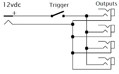
As the schematic, on the right, shows the power brick connects to the barrel connector at "12vdc". This makes 12 volts available on the input side of the switch at "Trigger". When the switch is closed it passes 12volts to the four "Outputs", which in turn send the voltage out over your trigger cables to wake your devices.
The four 3.5mm output connectors are simply connected in parallel. The +12 volts goes to the TIP connection and the common connection goes to the SLEEVE on each connector. If you want to add more outputs, just follow the first 4 and connect them all in parallel.
You will notice that I have used stereo output connectors and left the RING connections open. This is a safety consideration. Should someone plug in a stereo cable, the box won't end up shorting the RING to ground.
Getting the case ready
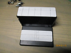
When I do a project that requires a case and especially when it requires connectors and other parts that are accessible from outside the case I generally follow a 3 step process. First I make a "sky plan" placing the connectors and other bits on the outside of the case to see what will fit where and how to make the best arrangement. Then, after deciding on a layout I will markup a sticker on the case to correctly align things and give me a drilling/cutting guide. Then finally I will get the tools out and make all the holes and openings.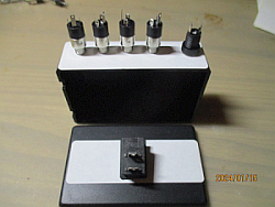
Assembling the case
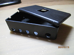
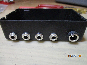
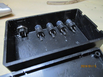
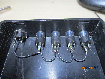
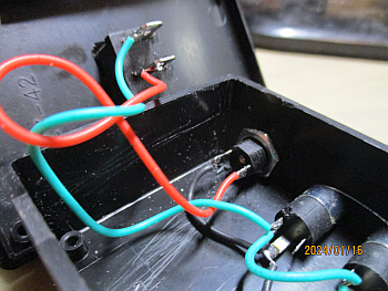
It is not uncommon to find one or two duds in a bargain bag parts purchase, making it worth the time to be extra careful. So as a final check before I start assembling the case, I will check all the connectors, switches, etc. to be sure they are all working as they should. In particular I will insert a plug into each jack to be sure it fits properly and, in this case, test the switch to be sure it opens and closes properly.Below is a photo of the case with the connectors assembled to it. Beside that is a view of the interior of the case. Please note that I've taken some care to orient the 3.5mm connectors all in the same way. This will help with the wiring task to come next.
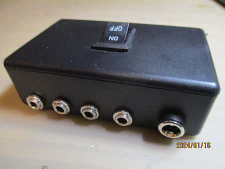
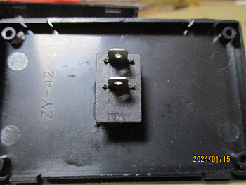
The next two pictures are the switch mounting on top of the case. If you are using a switch with the on and off positions marked, be sure to orient it so that the On position is toward the back of the case, where the connectors are.
Wiring and testing
Audio connectors vary in both appearance and layout. So the best way to wire this up is in three distinct phases, discovering your connections as you go.
 Starting with the negative lead...
- Connect the 12 volt brick to the barrel connector and plug it in.
- Using your multimeter determine which of the pins inside the case is the negative lead. if you touch the pins with your meter on the voltage scale and read a positive voltage, the negative will be on the meter's black lead.
- Disconnect the power brick.
- Now plug in a trigger cable to a 3.5mm jack.
- Using your meter on ohms/continuity scale, touch the sleeve of the open connector and probe to find which pin of the 3.5mm connector you used is the sleeve. You should read 0 ohms or hear a beep when you find it.
- Unplug the trigger cable.
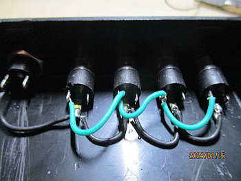
- Now daisy chain your hookup wire from the negative pin of the barrel connector to the sleeve pin of each of the 3.5mm connectors and solder.
 Now for the positive lead...
- Plug a trigger cable into one of the 3.5mm connectors
- Using your meter on the ohms/continuity scale, touch the open tip of the trigger cable and probe the connector you used to find which pin is connected to the tip. You should read 0 ohms or hear a beep when you find it.
- Unplug the trigger cable
- Now daisy chain hookup wire to the tip pin of each 3.5mm connector and solder.
 Finally the switch...
- Using a longer length of hookup wire connect the tip pin of the first 3.5mm jack to one side of the switch.
- Using a longer length of different coloured hookup wire connect the positive pin of the barrel connector to the other side of the switch.
As a final check, with the switch off, test for continuity at each point along each colour of wire. Also test for shorts between the wire colours. If all goes well your Hub is now ready for it's final live test.
Now hook up your power brick to the barrel connector. Connect a trigger cable to one of the 3.5mm jacks. Using the dc volts scale on your meter touch the open end of the trigger cable with your negative lead on the sleeve and positive on the tip . With the switch off, you should read almost nothing. Turning the switch on you should see +12 volts on the tip of the trigger cable. Repeat the 12 volt test for each of the 3.5mm output jacks.
If all went well ... Congratulations! It works.
Now you can close the case and see the finished project.
Using the hub
 This is the fun part. Using the 4 outputs of the Trigger Hub, you can control up to 4 devices in your system from the switch located on top of the hub.
Plug in your 12 volt power brick and connect it to the hub's barrel connector. Then from each of the 3.5mm output ports, connect a trigger cable to the trigger input of your devices.
When properly connected, turning on the switch on top of the Hub should also turn on all the devices connected to it at once. Turning off the switch should let them go back into standby mode.
DIY trigger cables
Trigger cables are nothing special. They handle 12 volts, typically at about 20ma of current. So there's no need for heavy cables or fancy connectors. You can make your own, at convenient lengths, very easily with low cost Connectors and Twin Lead from Amazon and other sources.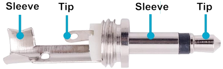
Just solder them up tip to tip and sleeve to sleeve. Use a multimeter to check for shorts across the tip and sleeve and for continuity from tip to tip and sleeve to sleeve.
Summing up
The 12v Trigger Hub is an easy project for DIY beginners. All you need is a little soldering skill, a multimeter and basic hand tools.For equipment with Trigger Inputs, the hub will let you automate the power on and power off of your system from a single switch.
Why these are not commonly available on line and in stores is something of a mystery to me.