
An Op-Amp Primer
 An Operational Amplifier (Op-Amp) is a chunk of easily controlled gain. They are used in all sorts of applications ranging from audio to radio to industrial instrumentation. In audio they are dominantly used to amplify signals, to buffer or filter the audio waveform. In fact, most class AB power amplifiers are actually high powered op-amps.
By itself the op-amp has enormous gain, often 60db (1,000x) or more. Thus, its actual behaviour in a circuit is determined by external components surrounding it. Negative feedback is used to adjust it's gain and frequency response to the specific application. Differing configurations of resistors and capacitors will determine if the output is inverted or not, how much gain is produced, the frequency response, and so on. This makes the op-amp a nearly universal building block for an amazing range of applications.
But "nearly universal" does not mean "all the same". In fact there are dozens of different op-amp designs, each with their own set of features, each made for a different task. In general, home audio equipment will use either general purpose parts or those designed specifically for audio applications.
Symbols and pins
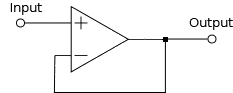
 The schematic symbol for an op-amp is shown on the right. As you can see, there are two inputs. The one marked plus does not invert; feeding a positive input here will result in a positive output. The one marked minus is an inverting input; if you feed it a positive voltage it will appear on the output as a negative voltage. It's a clever design that lends itself well to a huge number of applications.
To work the op-amp needs a source of filtered and regulated DC current. This is noted as Vs+ or V+, for positive and Vs- or V- for negative voltages. The safe range is typically plus and minus 5 to 15 volts. Some specialized op-amps have different voltage limits, some as low as 3.3 volts. They can also be used with a single supply voltage, by feeding the positive supply on Vs+ and grounding Vs-. In modern audio devices, many op-amps work from single +12 volt supplies.
Most Op-Amps are packed into an Integrated Circuit (IC) chip. These chips bring the signal and power lines out to pins that attach it to the printed circuit board. The most common arrangements are single, dual and quad packages:

These chips can be socketed, soldered, or surface mount types. Many modern pieces of audio gear feature socketed dual op-amp chips (the center pinout) that can be replaced by the end user.
How it works
An operational amplifier is designed with differential inputs. One inverts and the other does not. The internal circuitry is arranged so that, with feedback applied, if you put a signal into one input it will attempt to balance the other input to the same voltage. That is, the voltage across the inputs will always be nearly zero.By surrounding the Op-Amp with resistors and capacitors, we can control how it does that.
Yes, it really is that simple.
Basic configurations
The joy of working with Op-Amps is that with just a very few external parts you can create numerous different configurations. With just two resistors you can create buffers, amplifiers and inverting amplifiers.
 Buffer amplifier
This is far and away the simplest useful configuration for an op-amp. If we feed in a 1 volt signal to the non-inverting input, we will cause the output to move positive. Without feedback the amplifier's native gain would send the output to it's maximum. But, when we add feedback from the output to the negative input, the amplifier is going to balance the inputs by moving the output up by 1 volt. This gives us a unity gain amplifier.
 Non-inverting amplifier
Next, if we want to get some gain from our op-amp we can add a couple of resistors into it's feedback loop. The resistors act as a voltage divider, reducing the amount of feedback sent to the inverting input. Now if you put 1 volt into the input, the op-amp will try to balance it's inputs to 1 volt, but it only gets a fraction of the output voltage. Balancing the inputs will thus require moving the output by more than the input, producing gain. The actual gain of this circuit is determined by the ratio of the values of R1 and R2. If, R1 is 20k and R2 is 10k the resulting gain will be (R1/R2)+1 or 3. So now when we put in 1 volt we get 3 volts out. It is interesting to note that because of the way the inputs balance themselves this circuit can never go below a gain of 1.
 Inverting amplifier
Sometimes we will want to invert a signal; put in a positive voltage and get a negative one in response. This is easily done by locking the op-amp's non-inverting input to a fixed reference voltage and feeding a signal into the inverting input. In this case R1 and R2 operate as a voltage divider between the input signal and the output. When we feed in a positive signal the output will move negative, trying to balance the inputs at the reference voltage. The resulting output is negative for a positive input, positive for a negative input. The gain will be R1/R2. If R1 is 20k and R2 is 10k we get a gain of 2. In this case, depending on the values of R1 and R2, it is also possible to have less than unity gain. When R2 is 20k and R1 is 10k, we get a gain of 0.5.
In the real world
Of course the real world is more complex than the basic configurations above. But, the core principles of operation remain the same. More complex configurations using capacitors as well as resistors can give you tone controls, high and low pass filters, balanced audio decoders and a whole lot more.As a simple example you can actually build and use, here is a line level adjuster. It features about 10db (voltage gain of 3) of boost or cut, so you can adjust the input level to a device that is over or under driven.
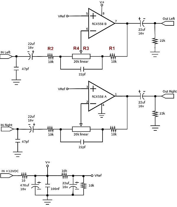
I've tagged the resistors in the feedback loop in the left channel for you. R1 and R2 behave the same as in the inverting amplifier above. R3 and R4 represent the values of the two sides of the potentiometer. R3 + R4 will always equal 20k. As we move the wiper from center towards the input R4 reduces and R3 increases in value. When moving toward the output the opposite happens R4 increases and R3 reduces.Thus the gain is (R1 + R3) / (R2 + R4).
When we adjust the 20k pot we get the following gain range:- When centered: R3=R4 so: (10k+10k)/(10k+10k) = 20k/20k == 1
- When at the input: R4=0, R3=20k so: (10k+20k)/(10k+0k) = 30k/10k == 3
- When at the output: R4=20k, R3=0 so: (10k+0k).(10k+20k) = 10k/30k == 0.3
If you have a scope and breadboard, this is a very simple learning circuit you can put together in a just few minutes.
The audiophile thing
 Many audiophiles like to tinker with their systems. This includes swapping out socketed op-amps in various devices in their systems. Given that this most often amounts to sending someone with zero technical training into an expensive device with tools in hand, a strong note of caution is in order.
- Get a chip extraction tool. Don't even think about using pliers or prying underneath with screwdrivers. Many good systems have been killed by the wrong tools.
- Follow the manufacturer's recommendations for compatible chips. Just because it has the same number of pins, does not mean it will work.
- Download the data sheets for each of your op-amps and make sure they are pin compatible, have similar voltage requirements and are in the same ballpark for unity gain frequency response.
- Before you take anything apart, disconnect your device from all power, inputs and outputs. Never work on live circuitry.
- When removing the current chip, use the extraction tool with a gentle rocking motion to "walk" the chip up and out of the socket. Remember, you might want to put it back in.
- When inserting the new chip be sure to follow the same orientation as the one you took out. These devices have no protections against improper installation.
- Use a magnifying glass to confirm that all pins are correctly started into the socket before pressing the chip into place. It is very easy to fold a pin over, destroying the chip.
- Press the new chip into place with gentle pressure. Do Not force it.
Now comes the big takeaway from all this:
As explained above, the behaviour of these chips is governed by the parts surrounding them. Replacing the chip, by itself, will not change this behaviour. Other than a slight improvement in noise floor or distortion, it is very unlikely that swapping chips is going to make any appreciable difference. In fact, you could build my example circuit above using any of a couple of dozen different op-amps instead of the RC4558 specified and nobody would even notice.
Summing up
Op-Amps are audio workhorses. Almost all modern equipment uses them. This overview should give you some beginning idea how they work and why they're so popular.If you want to delve deeper, try Operational Amplifier Basics on the Electronic Tutorials website.